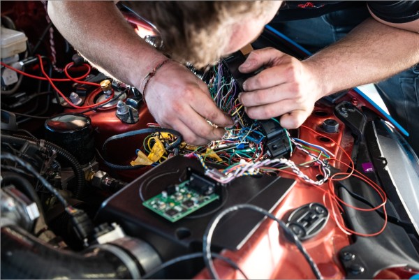
With almost every customer conversion, we are asked about the connection plans for the boost pressure control valve, intake air temperature sensor and a vacuum plan. So today's blog deals with exactly this topic: How to properly connect the vacuum lines and the sensors when doing a turbo conversion!
Vacuum lines:
To basically connect the new vacuum lines on the ECU and on the boost pressure control valve, use two free 4mm vacuum connections on the intake manifold behind the throttle body (i.e. the side that sits between the throttle body and the engine). Guide one of the new vacuum hoses through the bulkhead on the passenger side into the interior and connect it to the control unit's MAP sensor. You can secure the ends of the vacuum hose to the connections on the MAP sensor and intake bridge with small zip ties.

The second new vacuum hose on the intake manifold then leads to the boost pressure control valve at the connection under the electric connector of the boost pressure control valve. Instead of starting from the intake manifold (if available on the respective turbo), this can also simply be connected from the connection to the turbo outlet on the pressure side. This has the advantage that no vacuum line has to be pulled across the engine bay. So if this vacuum connection is available on your turbocharger, it can simply be used and the intake manifold can remain plugged. The vacuum hose can then also be secured on the connections with small zip ties. Last but not least, a vacuum line between the outlet of the boost pressure control valve (connector pointing upwards) and the wastegate of the turbocharger has to be installed. This line can then also be secured with small zip ties.
Electrical connector of the boost control valve:
Now we can connect the boost pressure control valve to the existing wiring harness. Here you always use the cables of the purge valve in the engine compartment.
MX-5 NA:
Positive supply: white / red cable of the purge valve
Ground signal: yellow / red cable of the purge valve
MX-5 NB:
Positive supply: white / red cable of the purge valve
Ground signal: green / black cable of the purge valve
MX-5 NBFL:
Positive supply: white / red cable of the purge valve
Ground signal: green / yellow cable of the purge valve
Electrical connector of the IAT sensor:
Finally, we connect the intake air temperature sensor to the existing wiring harness. For this purpose, different sensors are used in the different models, for the cables of which we use for the new IAT sensor. The cable colors of the MX-5 NA were often swapped, but we have listed the most frequently used cable colors here. However, it can happen that the cable colors on your vehicle are different. The pin assignment is irrelevant here, as the temperature sensor is a simple resistor.
MX-5 NA 1.6L:
Red/green and black wire with additional color (mostly green) of the air flow meter
MX-5 NA 1.8L:
Red/black and black wire with additional color (mostly blue) of the air flow meter
MX-5 NB/NBFL:
Use the two cables of the original intake air temperature sensor (on the side in the air filter box). The original air flow meter is completely omitted here.
You are currently doing a turbo conversion on your MX-5 and the instructions did help you? Or do you still have unanswered questions? Just write it in the comments and we'll be happy to help!
Your SPS Motorsport Team

