
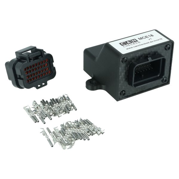


CANchecked CAN Bus Extension Module MCE18
- Order number: 248487
If you have any questions about TÜV registration or orders to Switzerland, please do not hesitate to contact our competent partners in the respective country:


WITH ECE APPROVAL

WITH ECE APPROVAL


WITH TÜV PARTS CERTIFICATE!


5% Saved
SINGLE REGISTRATION IN OUR HOUSE!

 NA/NB/NBFL")


")

Single registration in our house

Single registration in our house


no registration required


WITH TÜV PARTS CERTIFICATE!

5% Saved
SINGLE REGISTRATION IN OUR HOUSE!


")


Single registration in our house

WITH TÜV PARTS CERTIFICATE!

Approval in preparation

